Getting Started
Get the Hardware
The hardware is open source which allows you to download the Gerber files and KiCad files and have the board produced by a manufacturer of your choosing. You'll also need this compatible display.
Alternatively you can just:
Buy the Board and Display HereInstall Arduino Library
Arduino IDE
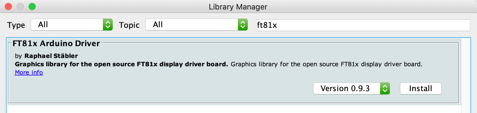
In order to install the FT81x Arduino Driver using the official Arduino IDE, navigate to Tools → Manage Libraries... and search for the FT81x Arduino Driver:
After you installed the latest version, you can use the library either by navigating to Sketch → Include Library or go to File → Examples → FT81x Arduino Library to load one of the example sketches.
PlatformIO
The library is available on the official PlatformIO registry. To install it, just run the following command in your project folder:
pio lib install FT81x_Arduino_Driver
Hookup
Pin Description
Please refer to the following pin description when hooking
up the board to your microcontroller:
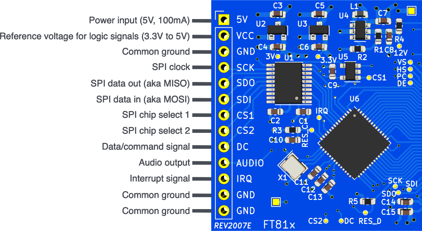
The table below prodives a more detailed description
for each pin.
| # | Name | Description | Required |
|---|---|---|---|
| 1 | 5V | 5V power input for powering the the board, the display and the backlight LED. Hook this up to the 5V power outlet of your Arduino board. Requires at least 100mA of current. | |
| 2 | VCC | Reference voltage for all digital signal lines. For 3.3V microcontrollers, hook this up to the 3.3V power outlet of the Arduino board. For 5V microcontrollers, hook this up to the 5V power outlet. | |
| 3 | GND | Needs to be connected to a common ground with the Arduino board. | |
| 4 | SCK | Clock signal for the SPI bus. Hook this up to the SPI clock of your Arduino board. | |
| 5 | SDO | Serial data out of the board. Hook this up to the serial data in signal of your Arduino board (aka MISO). | |
| 6 | SDI | Serial data in of the board. Hook this up to the serial data out signal of your Arduino board (aka MOSI). | |
| 7 | CS1 | Chip select signal for communication with the FT81x IC on the board. It's recommended to hook this up to the default CS pin of your Arduino board. However, any GPIO pin can be configured as CS1 signal. | |
| 8 | CS2 | Chip select signal for communication with the integrated controller IC of the display. Any GPIO pin can be configured as CS2 signal. | |
| 9 | DC | Data/command signal for communication with the integrated controller IC of the display. Any GPIO pin can be configured as DC signal. | |
| 10 | AUDIO | The FT81x is capable of sound synthesis and mono audio playback. This pin is directly connected to the raw audio output of the IC. It's recommended to use additional filter and amplification circuitry for proper audio applications. | |
| 11 | IRQ | Interrupt signal for different applications (e.g. audio playback). As of now, this signal line isn't used by the Arduino library. | |
| 12 | GND | An additional common ground. It's only required that one of the GND signals is connected. | |
| 13 | GND | An additional common ground. It's only required that one of the GND signals is connected. |
Common Boards
Please refer to the table below for specific information on how to hook up the display driver board to common Arduino boards.
| Name | Arduino Uno | Arduino Nano | NodeMCU-32S | Teensy 4.0 |
|---|---|---|---|---|
| 5V | 5V | 5V | 5V / VIN | VIN (5V) |
| VCC | 5V | 5V | 3V3 | 3V |
| GND | GND | GND | GND | GND |
| SCK | 13 | D13 | GPIO18 | 13 |
| SDO | 12 | D12 | GPIO19 | 12 |
| SDI | 11 | D11 | GPIO23 | 11 |
| CS1 | 10* | D10* | GPIO5* | 10* |
| CS2 | 9* | D9* | GPIO17* | 9* |
| DC | 8* | D8* | GPIO16* | 8* |
* configurable
Hello World
After you successfully installed the Arduino library and hooked up your board, create a new Arduino Sketch and enter the following source code. Be sure to use the correct pin numbers for the CS1, CS2 and DC pins on line 3.
HelloWorld.ino
#include "FT81x.h"

FT81x ft81x = FT81x(10, 9, 8);

void setup() {
    SPI.begin();
    ft81x.begin();

    ft81x.beginDisplayList();
    ft81x.clear(FT81x_COLOR_RGB(0, 0, 0));
    ft81x.drawText(240, 200, 31, FT81x_COLOR_RGB(255, 255, 255), FT81x_OPT_CENTER, "Hello World\0");
    ft81x.swapScreen();
}

void loop() {
    // do nothing
}
After compiling and uploading to the mictocontroller, you should see the text Hello World at the center of your display.
Refer to the various example sketches as well as the API documentation for more information.
If you have any issues and you already double checked all the connections and the code contact the seller or open an issue on GitHub.
Audio Setup
The FT81x Arduino Driver has support for mono audio output with its integrated sound effects as well as audio playback capabilites. To make proper use of this, an audio filter and amplifier circuit is required.
For prototyping purposes you can create a simple circuit using the LM386 audio amplifier IC:
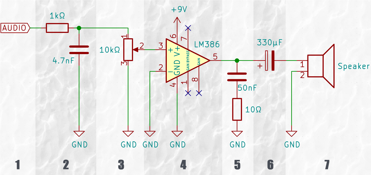
The circuit above consists of the following parts:
- The audio input signal coming from the FT81x Arduino Driver board.
- A low pass filter for filtering all the high frequency switching noise.
- A 10kΩ potentiometer to act as a volume control.
- The LM386 audio amplifier with a 9V power supply.
- A Zobel Network for impedence control of the speaker.
- A polarized capacitor to block DC current.
- A loudspeaker for the final audio output.
Some additional notes:
The power input of the
LM386 may be increased up to 12V for less distorted
output.
The value of the polarized capacitor in (6)
can be anything from 220µF to 1000µF.
The above schematic laid out on a breadboard may look like this:
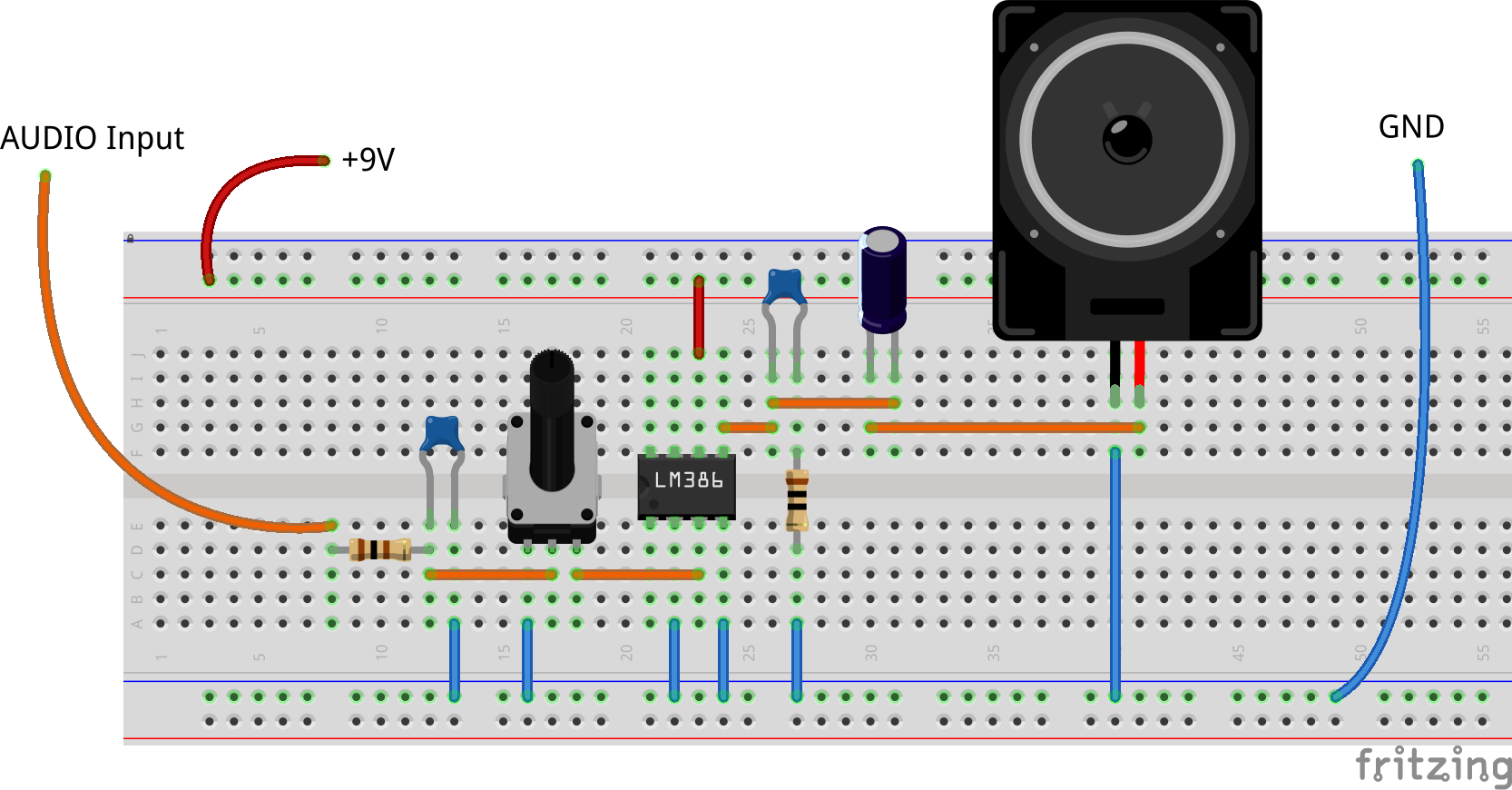
Be sure to connect all GND lines together and connect the audio output of the FT81x Arduino Driver board to the audio input of the amplifier circuit. Also, beware of connecting the 9V power supply to anything other than the LM386 as it may permanently damage the FT81x Arduino Driver board!
In order to test this setup, check out the Sound Effects Example Sketch of the Arduino library.